Fiber Testing
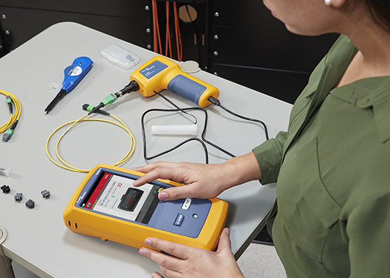
Fiber testing and inspection is a critical step to verifying network performance, to comply with standards and warranty requirements, and a tool to diagnose, repair and re-verify a network once it’s been activated. The need for accurate testing has been exacerbated by diminishing loss budgets and increased demands on networks.
High losses and optical network failure are often caused by contaminated, damaged or poorly polished connectors, poor splices, and micro or macrobends introduced in shipping or installation. The best way to keep your network running efficiently? Test and inspect.
Fiber Testing FAQs
How do I plug an MPO connector into my OTDR?
Many OTDRs have only one plug connector, which can make plugging in your MPO confusing. Luckily, there are different ways to connect your OTDR to the MPO connector. If you want to see the MPO connector, you’re going to need a launch fiber. That launch fiber is going to need to have the same MPO connector. If you’re doing 12 fiber, you need a 12 fiber MPO launch. And if you’re doing 24 fiber MPO, you’re going to need a 24 fiber MPO launch cable. The length of that cable is going to be a function of the distance of the fiber you’re testing, or the pulse widths that you’re using. If you’re using a short pulse width, a three or a five nanosecond, maybe a 10 nanosecond pulse width, you can get by with a pretty short launch fiber. Longer the better, but say at least 20 or 30 meters. Now on the OTDR end of that launch fiber, you could either have it be a fan out cable, or you can put a cassette there and move through the ports of the cassette. Also, there are manufacturers who make a switch. The switch has say an SC port and inside the switch it will move between 12 or 24.
Is there a difference between a PON power meter and a ‘regular’ power meter?
Yes, there are several differences. First, the PON power meter is a pass through device which measures the power of the downstream signal and the power of the upstream signal. A regular power meter is a single ended detector, so you can measure the downstream power, but then you can not validate that your ONT’s properly emitting because you cannot measure the upstream. That’s the first difference. Also, on your PON power meter you have preconfigured thresholds for the different wavelengths according to the different PON layers that you could have GPON, XGS PON, and GP PON2, all of those.
What is the number one cause of network failure?
The leading cause of network failures is dirty connections. Almost all the time, the dirt is completely invisible to the naked eye, but since the diameter of a fiber core is so small (50 microns for multimode fiber and only 8 microns for singlemode fiber) it doesn’t take much to block the light on the fiber endface.
When the dust cap is removed the ferrule end face can easily be contaminated by direct contact with skin oil, grease, salt, fingerprints, lint, uncured epoxy, grime or dust. Even just open air exposure may result in moisture and dust sticking to the end-face. When the dust caps are off your connectors are at risk of contamination.
This is why proper inspection and cleaning techniques are so important, especially with today’s tight loss budgets where too much loss from a dirty connection can have a direct impact on bit error rate, insertion loss and optical return loss which will impact system performance and reliability.
How do you test a POL network?
Since the POL is an enterprise adaptation of the GPON used in Fiber-to-the-Home applications, you can use the same tools and expertise that were developed for GPON.The recommended testing protocols for a passive optical LAN deployment are:
- Inspecting the connector
- Fiber characterization, with different tools like OLTS, OTDR, iOLM
- Validating service activation using a PON power meter
- Reporting tests and test results
In fiber optic networks, 80% of the problems are caused by dirty or damaged optical connectors, 10% of network problems are due to macrobends, which are responsible for signal loss and network quality deterioration, and the remaining 10% of problems can be attributed to other components – the ONT, the OLT and the splitters.
What’s the difference between Tier 1 and Tier 2 Testing?
Tier 1 testing looks at loss, length and polarity. While Tier 1 fiber optic tests can identify problems in terms of pass or fail, they cannot determine the root cause or location of the problem. Tier 2 fiber optic testing is used to pinpoint root-cause locations and the amount of loss and optical return loss (ORL) from each problem contributor and is performed selectively in addition to Tier 1 testing under specific conditions and situations. Tier 2 fiber testing provides a deeper level of link visibility unlike any other fiber infrastructure tests. The optical time-domain reflectometer (OTDR) is used to perform Tier 2 fiber optic testing.
RECENT WEBINARS
-

LAN Standards, News & Trends: 2025 Update
Join FOTC's Standards Chair, Cindy Montstream, for an update on important LAN Standards. Cindy will cover TIA standards, IEEE standards…Read more -
The Perpetual Perplexities of Optical Fiber Polarity
Optical Fiber Polarity is an essential design and implementation process necessary to ensure the proper functioning of all optical networks.…Read more -

Tales from the Field: The Top 5 Mistakes and How to Avoid Them
This presentation addresses some of the most common mistakes we see in the field and how to avoid them. Topics…Read more -

TIA-942-C Data Center Standard: What’s New?
The recent revision to ANSI/TIA-942-C addresses the evolving needs and challenges of modern data center infrastructure by incorporating new technologies…Read more
RECENT ARTICLES
-

Artificial Intelligence Needs Glass
With large language models that power systems like ChatGPT increasing in popularity – the AI text-generating website saw 1.6 billion…Read more -

Connecting the future—from cloud to edge
All around us, technology is rapidly evolving, and its capabilities are continuing to become a part of everyday life. Advanced…Read more
RECENT WHITE PAPERS
-

Types and Locations of Edge Data Centers: Scoping Locations That Work for Your Needs
To meet the needs of new applications, data needs to be hosted very close to users and network functionality needs…Read more -
Fiber Contamination, Inspection & Cleaning
Despite industry best practice of inspecting and cleaning fiber optic endfaces, contaminated connections remain the number one cause of fiber…Read more