With increased service demand is driven by an uptick in teleworking, distance learning, and online socializing trends, reliable network connectivity has never been more important. At the same time, with the advent of 5G mobility, high-speed networking, and inherently more complex and dense networks, service providers are facing new challenges in delivering those complex offerings and data reliably to customers.
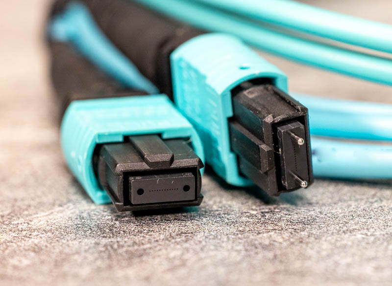
Multifiber push-on (MPO) connectors are becoming increasingly popular to save space in fiber-dense environments and for their many advantages for high-speed network operators, owners, and installation companies. MPOs are used in connecting the fastest links that deliver the most sensitive services and data to customers, enabling high-speed interconnects and creating redundancy. MPO connectors are mostly found in data centers, although many telcos are currently reconfiguring their central offices into data centers (CORDs) and deploying MPO cables with 12 or, increasingly, 24 fibers.
NTT-Advanced Technology Research cites that 80% of network problems are due to dirty connectors, and the No. 1 cause of network failure is contaminated connectors. For MPOs, inspection and cleaning become even more critical. Given that a single dirty or damaged connector can impact 24 fibers—or more—with MPO connectors, taking critical communications lines out of service for troubleshooting will cause service interruptions for numerous customers.
How can the performance of MPO links be ensured? It all starts with testing. There are the five essential things you need to do: connector inspection, proper cleaning, polarity-type validation, continuity confirmation, and choosing the right referencing method.
- How to inspect MPO connectors?
Connector inspection can be done using a fiber inspection scope, which is a specialized microscope that takes a picture of the connector end-face on top of which an analysis algorithm is applied to provide a diagnosis. No matter how good the analysis algorithm is, if the picture lacks quality definition, achieving accurate results remains a challenge. Getting reliable inspection results is more complicated for multi-fiber than for single-fiber connectors.
When selecting an inspection solution, pay attention to the optical assembly. Look for high-definition images with a sharp contrast between light and dark areas. This way, when running the analysis on top of that image, the scope will properly distinguish defects and scratches on the surface of the connector from other things such as reflections to correctly diagnose issues.
For MPO inspection, a connector inspection scope with larger lenses is more likely to provide better image clarity. Try to avoid deformable lenses as they often do not provide the level of detail needed to yield reliable and repeatable results.
Complementary metal-oxide-semiconductor (CMOS) detector technology has advanced in recent years, driven by applications such as autonomous vehicles and facial recognition. Next-gen CMOS detectors contribute to obtaining a larger field of view, which is necessary to capture the entire surface of the multi-fiber connector. While connectors with more than two rows of fiber are not yet common, they are emerging, and a good inspection scope should have a field of view that is large enough to see up to 4 rows of 12 fibers on a single connector.
A uniform level of light should shine across the whole surface of the MPO connector to avoid zones with shadows on the surface and for better visibility. LEDs used for fiber end-face inspection are traditionally in the blue spectrum at 435 nm, which is perfectly good for single fiber connectors. However, MPO connectors require greater contrast on small details. LEDs in the violet range at 405 nm can identify extremely small defects—as small as 2 µm—which is about 35 times smaller than a human strand of hair.
Speed of testing is always an issue, especially in data centers where a high volume of multi-fiber connectors must be inspected. The inspection of one MPO connector typically takes about one minute from the moment a connector is inserted, to the analysis and saving of results. Newer solutions have automated every step of the operation and inspection time has been significantly reduced, some completed in less than 10 seconds.
Switching between an MPO and LC adapter (or any other single-fiber connector type) also contributes to the complexity and inefficiency of inspecting connectors. Look for solutions that have a long reach nozzle by default, with as few adapters as possible, if the tip changing can be done with one hand without any parts coming loose in the process.
Once the correct tool is selected, connectors must be inspected at the installation phase. Otherwise, operators will have to shut down live links to fix problems when they arise in the future.
Inspection can detect any imperfections and determine if connectors are clean. Connectors that fail inspection due to contamination can be cleaned and those with scratches or other physical damages can be replaced without impacting the network.
Connector validation is key because dirty or damaged connectors have a direct implication on insertion loss and optical return loss levels. This in turn impacts bit error rate (BER), system performance, and network reliability. Slower speeds can tolerate connectors that are not in perfect condition, but high transmission rates such as 25, 40, 100, or 400 Gbit/s (which are often the rates going through MPO cables) have an extremely small margin of error.
There are many sources of contaminants for connectors. Handling connectors can impart skin oils and particles or dust. And even well-protected connectors can be contaminated by their own dust cap because of static electricity.
Dirty connectors can potentially still be useful if cleaned properly and re-inspected. The IEC recommends several attempts to clean before rejecting a connector.
Inspection at the installation phase is even more critical for MPO connectors to ensure that faulty connectors are discarded before deployment, and to catch and clean dirty connectors.
- How to make sure an MPO connector is clean?
Simple: Inspect, clean, reinspect.
Once you have confirmed a failed diagnosis, try cleaning the connector. While there are multiple tools available, cleaning an MPO connector has always been tricky. The dry method should be the first to be used. A clicking cleaner pen or dry wipes can be used. Simply push the pen against the connector until you hear a click and it’s done.
The best practice is to perform up to three cleaning attempts before replacing the connector or the entire cable. Yes, replacing the cable can save the trouble of cleaning the connector, but multi-fiber cables are expensive, and this can increase capital expenditures in the long run.
Attempting to clean a connector when not necessary can make the situation worse. This is especially true in the case of highly sensitive MPO connectors where, for example, dirt from the first row could potentially migrate to the second row while cleaning.
Make sure to inspect both mating connectors, as residue from a dirty connector will transfer to a perfectly clean connector once they mate. If the dry method fails to remove the dirt, try the hybrid cleaning method, which involves using a solvent. Thereafter, make sure the connector is fully dry before mating it.
It is crucial to use the right cleaning method and tools. For example, if cleaned with inadequate tools or cleaned with a wet cleaner but not dried properly, the connector may remain dirty.
Always reinspect the connector after cleaning to ensure the dirt did not transfer from one fiber to another.

- How to test polarity?
Polarity simply refers to the way fibers are arranged inside the cable. According to Navigating MPO waters: 2018 survey, 30% of MPO cable users report confusion in determining polarity type.
During installation, MPO connectors must be properly aligned and mated, which is not as simple as it sounds. Ensuring accurate polarity for MPO fiber array cables is a big deal and can be complicated, due to multiple polarity schemes available for these connectors and polarity flipping during connecting and installation.
Three different polarity types, corresponding to different cable structures, are used with MPO cables. Validating the polarity ensures that signals are traveling in the correct path and that connections between the transmitting and receiving ends are intact.

When testing polarity, your main goal is to make sure the right transmitter (TX) is sending signals to the right receiver (RX). To accurately send and receive data, MPO connectors must be properly aligned and mated. A bad coupling will impede signal transmission, as the signal could be sent in the wrong direction.
Undiagnosed polarity issues increase CAPEX and workload for technicians (i.e., OPEX). Technicians may unnecessarily rip and replace expensive MPO patch cords, believing they are faulty, when in fact they simply did not have the expected polarity type. If polarity issues are not caught and corrected before turn-up, then trying to pinpoint which cable connections have polarity problems after they have been installed becomes a frustrating and tedious guessing game.
- Testing continuity
Confirming the continuity of a link ensures that there is no break and that light travels properly all the way to the end of the link. It’s a quick validation test that, when done during installation, can save a lot of hassle later. A light source or a visual fault locator can be used to perform this test, which consists of sending light in the visible spectrum at one end of the cable and simply confirming that the light is also visible from the other end.
- How to perform Tier-1 testing on MPO cables?
According to the TIA-568: Optical Fiber Cabling and Components Standard, Tier-1 certification consists of testing installed optical fiber cabling for attenuation with an optical loss test set (OLTS) and verifying the cabling length and polarity. The insertion loss (IL) measurement is essential to verify if the link meets the expected loss budget. MPO cables also must be Tier-1 certified to ensure optimal link performance.
An OLTS includes an optical power meter to measure received optical power and a light source that closely resembles a system transmitter (e.g., an LED for multimode optical links, a laser for single-mode optical links). An OLTS may be a single, integrated instrument or an optical power meter and a light source used in pairs.
It’s critical for operators to have accurate and valid measurements but even using the right test equipment isn’t enough—you also need to choose the best reference technique. Although test equipment may come preconfigured with specific reference routines, this doesn’t mean they are ideal for every network setup and test situation.
So, which reference method is best for your needs? Here are the differences between the one-cord, adapter cord, two-cord, and three-cord reference methods recommended by various standards organizations.
One-cord reference method: This method is the most used in the industry because it yields highly accurate results and is recommended by the TIA and IEC. The reason? It enables operators to test the end-to-end fiber optic link, including losses from connectors.
Adapter cord: This method only includes the first or last connection in the loss budget. This is mainly used for MPO cables, as it is designed to match the connector gender – male (pinned) or female (unpinned) – with the port on the test units.
Two-cord reference method: This reference method is used mainly when the connector on the power meter is different than the one on the fiber link to be tested. It generates less accurate results since it uses a hybrid test cord to match connector types and includes a connection mating in the reference.
Three-cord reference method: If the connectors at both ends of a device under test are different, a three-cord reference method may be used; however, the connector state can greatly impact measurements, particularly if the connectors are dirty, old, or damaged.
Once the reference method is selected, it is crucial to execute it perfectly as this is where most errors occur. A bad reference will result in bad measurements, so make sure to select a test set that includes an onboard reference assistant to ensure the reference is done correctly.
Conclusion
In short, Tier-1 certification and connector inspection are essential when installing MPO cables. Keep accuracy and ease of use in mind when selecting test equipment to steer clear of human errors and minimize the chances of a network outage.
This article, written by Guillaume Lavallee, originally appeared in TodoFiberOptica.